
When moving from one element to the next element, the default movement trajectory is the shortest straight line between these two elements. The collision must occur if there is an obstacle between these two elements. So the Goto points must be set on the movement trajectory to avoid the collision. As shown below:
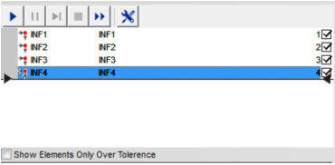
The steps of setting Goto points are as follows: To make the lens bypass the obstacle from the point A to the point D, you must move the lens along the point in the order of AàBàCàD, and click the Goto point button at each position of A,B,C,D. All the Goto points will be shown in the element list area. The machine will move along the Goto points when the program is running
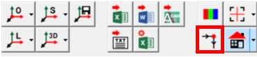
You can get a picture of the workpiece (especially the large size workpiece) by the way of scanning or taking pictures, and make the pixels of the picture correspond to the coordinate points of the actual workpiece, then you can quickly locate the position of the workpiece by taking the picture as an image navigation, right-click at any point on the picture in the image navigation window, and select the "move here" menu option, the machine will automatically move this point of the workpiece image to the center of the image area.
The image navigation function is usually used for the large-size workpieces and the workpieces with a lot of similar features.
Making a picture with integral scanning
Step 1: Click the "Image Navigation" tab under the graphics area, switch to the image navigation window, click the "scan workpiece" button, and then it will pop up the "Scan Workpiece Setting" dialog box.
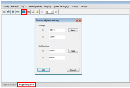
Step 2: Move the top left corner of the workpiece image to the center of the image area. Click the "Read" button at the top of the dialog box to read the coordinates of the top left corner of the navigation picture (Note: Do not close the "Scan workpiece Settings" dialog box now).

Name: Mikrosize
Mobile:0086-13918745376
Tel:0086-769-85331789
Email:mikrosize@188.com
Add:NO7 East Xingfa Road Wusha, Changan Town, Dongguan, China.
 Microsize
 Microsize