
The XY plane of the workpiece coordinate system used by the user is usually parallel to the XY plane of the machine coordinate system, in this case, the steps to create a workpiece coordinate system are as follows:
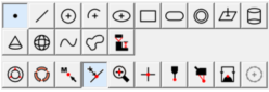
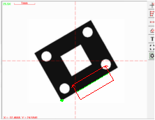
Step 1: Extracting or constructing the elements used to create the coordinate system.These elements include the element to establish the coordinate origin and the element to establish the axis direction. Fox example, extracting a datum point and a datum line as follows:
Step 2: Establishing the workpiece coordinate system origin : Select the "PNT1" element in the element list area as shown below, click the button on the coordinate toolbar, and then the coordinate symbol will appear immediately in the position of "PNT1"。
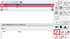
The element used to create the coordinate origin can be a point or other geometric elements. The software will take a point or automatically extract the center points of other geometric elements as the coordinate origin. as shown below
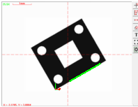
Step 3: Axis alignment: Select the "LIN1" in the element list, click the button on the coordinate toolbar, The software will make the direction of a coordinate axis parallel to the "LIN1". The X-axis color of the coordinate symbols is red, and the Y-axis color is green. By default, the software align the axis that its angle is relatively smaller with the "LIN1", it may be the X or Y axis. You can also click the triangle symbol on the right side of the button to chose to align the X axis or the Y axis.
Name: Mikrosize
Mobile:0086-13918745376
Tel:0086-769-85331789
Email:mikrosize@188.com
Add:NO7 East Xingfa Road Wusha, Changan Town, Dongguan, China.
 Microsize
 Microsize